|
|
Post by Andi on May 4, 2008 19:18:11 GMT -5
Unfortunately the problems with my Race 250 continue, following are the details: 1. I have absolutely no spark, hence the engine isn't starting. 2. Since new I had a problem where the plug after one run would foul and not start the engine, put in a new plug and it started just fine, but also after one drive no good again. I even tried a NGK D7EA instead of the D8EA and that seems to have lasted a little longer, maybe as its hotter it delayed fouling some, the fouling may be as a result of too weak a spark? 3. As well at high speeds it would bog down until backing off the throttle and would then run fine. 4. I've always suspected an ignition problem, but can't pin point where and unfortunately have no manuals or electrical wiring diagrams. Except for the YP250 Service and Parts Manuals, but the wire colors are different. 5. I've gone through some of the YP250 recommended ignition system checks: 1. Main Fuse (at battery) is OK - don't think there's supposed to be another fuse anywhere? 2. Battery tests OK - starter tumbles strong. 3. Sparkplug can't confirm if OK, but have two (2) new plugs and neither spark when tumbling engine. 4. Don't have ignition spark gap tester. 5. Sparkplug cap resistance test: YP250 spec = 5k ohm - Race 250 = 5.83k ohm. 6. Primary coil resistance test: YP250 spec = 3.6 - 4.8 ohm - Race 250 = 4.3 ohm. YP250 P/N 4HC-82310-00 Ignition coil assembly = Mitsubishi F6T507 ignition coil. 7. Secondary coil resistance test: YP250 spec = 10.7k - 14.5k ohm - Race 250 = 14.59k ohm. When I put on the sparkplug cap I get no reading however - I don't know if that is normal, the test is shown without the cap in place. 8. Pick Up coil resistance: If I found the correct thing, the resistance test shows no reading - which may then be my problem. I can't however find anything under pick up coil in the electrical of the parts manual unless its a YP250 P/N 5SJ-82305-10 ignitor unit. In the service manual the pick up coil is listed as a Mitsubishi J4T069 T.C.I. Unit. 9. The part I tested thinking it is the pick up coil has a only two wires out of three possible connected, picture (1) and (2) attached. It also has a green wire attached to the mounting screw, which I think also runs to the ignition coil mounting (it is the same green color wire at least), ignition coil picture (3) attached. 10. The same green wire on the pick up coil is life, with the ignition switch "ON". It sparks as you touch to the frame. 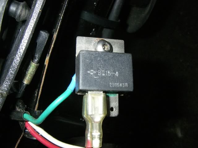 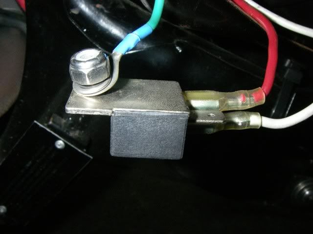 The green wire bend back, mounts with and eyelet on the ignition coil mounting bracket. 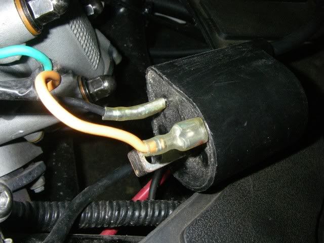 Any help would be sincerely appreciated. Andi |
|
|
|
Post by earlwb on May 4, 2008 19:33:27 GMT -5
Check your coil wire and make sure it is screwed in snug into the spark plug boot and the ignition coil. There is a small reversed sheet metal screw that you screw the wire onto in each item. A lot of people have had loose spark plug wires, sometimes the wire falls out too.
That weird thingie is a diode semiconductor that the show on the circuit diagrams. It should measure some resistance one way and infinite or very high resistance the other way. A diode only allow current to flow in one direction.
By the way, where is this diode located on your scooter?
The ignition pickup coil/sensor is located under the right side case cover adjacent to the flywheel and alternator.
A spark plug fouling would be because the engine is running too rich, or the rings are allowing too much oil blowby to get through to the combustion chamber.
I think the first is possible as the automatic enrichener heater coil may not be powered or broke, or it is stuck and not closing off the extra fuel port.
|
|
|
|
Post by Andi on May 4, 2008 21:58:12 GMT -5
Check your coil wire and make sure it is screwed in snug into the spark plug boot and the ignition coil. There is a small reversed sheet metal screw that you screw the wire onto in each item. A lot of people have had loose spark plug wires, sometimes the wire falls out too. I checked several times its all good and tight in fact I'm getting the spec resistance up to the cap, as well as the spec resistance through the cap. OK, thanks for the info, I know a diode is like an electric check valve only allows flow one way, didn't know this was it though. It is located on the frame to the right of the cylinder head close to the ignition coil. What's it for on this system? Then I should get continuity one way, but I'm not getting anything, I tried all how. Are you talking about part of the alternator, a lot of small bikes have one coil in the center of the stator for the ignition system and four or so wired in sequence for the AC current to run everything else? The pick up coil on the wiring diagram is completely separate form the AC magneto though. If the plug is not sparking strong enough couldn't that lead to fouling due to improper combustion especially when running hard? Please explain. I guess the "Ignitor Unit" as listed in the service manual is the CDI. The Pick Up Coil is also called the T.C.I. ? Thanks Andi |
|
|
|
Post by earlwb on May 5, 2008 9:43:44 GMT -5
yeah I was talking about the alternator as to the pickup coil/sensor for the CDI unit.
Yeah it doesn't sound good for the diode if it is reading infinite both ways.
The automatic enrichener unit (many people call it a choke), provides a little more fuel when the engine is cold. They have a heater coil that heats up and causes a wax like substance to expand, which pushes on a metal diaphram with a needle attached. When cold the needle is retracted and a extra fuel port is open allowing more fuel into the carb to flow into the engine's intake. When the needle extends out it closes off this extra fuel port, cutting off the extra rich fuel air mixture from the engine.
The automatic enrichener is the black cylindrical like thing sticking up at a angle from the carb.
It has two wires coming off of it to power the heater coil with.
|
|
|
|
Post by earlwb on May 5, 2008 9:54:53 GMT -5
I was thinking that a high power bridge rectifier with the 4 blade pins would work as you simply use two pins. But the tab is usually connected to the diode as well. So I'll need to think about that. They could have used a bridge rectifier as well, but I don't see what the third wire is for, as on my scooter's schematic, they don't use a third connection.
I can't identify that diode unit, the BQ15-4 doesn't correlate to anything that I know about. So I can't tell if it is a common anode or a common cathode for the metal tab on it.
There are a lot of diodes one could substitute for it, but I can't tell for sure as to which way to orient the replacement in relation to positive and negative.
|
|
|
|
Post by Andi on May 5, 2008 16:46:30 GMT -5
Earl, I don't think the diode is part of the ignition system, it is listed in the 2000 YP250 and it seems to tie into the starter and alarm circuit, but is not part of the starter or ignition system as per the diagram. I guess I will have to figure out if I'm getting current to the system and if not why, because the starter is tumbling just fine and I'm not getting a spark on the plug. Guess I should check the current supply to the CDI, working my way backwards through the system, as the coil is up to Yamaha specs. Right click the image, click view image and then zoom. Item 10 is listed as the diode:   Andi |
|
|
|
Post by Andi on May 22, 2008 20:28:38 GMT -5
I just finished some further tests on the scoot, as I mentioned already the the plug cap, primary and secondary, coil are to Yamaha specs.
I scrapped out the side panel, to get better access, in order to isolate the wiring and identified the pick up coil plug.
Now I mentioned before that electrical is my weak point and I dislike it, but it never hurts to learn and would make me that much more proficient at my job, so as today was a holiday it was the perfect opportunity to go through it.
As per Yamaha spec the resistance reading on the pick up coil is supposed to be 168 to 252 Ohm. When I first tried it I got about 237 Ohm which is good, but it only read for a second or so and then the display read I (infinite). Anytime I touched the probe on the connection again its the same thing, the reading briefly shows and then its gone. It doesn't stay continuously as with the coil and the more often I did it the lower the reading got all the way from 237 down to 87 and then up and down slightly, but never over 200 again.
I can only assume out of that the pick up coil is bad? I tried another multimeter to verify and the same thing happened.
Any advice? Is there anyway to check if current is getting to CDI and from there to the coil? If memory serves me correctly I need a peak voltage adapter for the multimeter in order to test the CDI and primary coil, the secondary coil due to the 15000 to 30000 Volts can't be tested with a standard instrument?
Could anybody tell me what the difference is between one make of CDI and coil set up versus another? Like Yamaha and Honda etc? Is it possible to take a CDI and coil form a similar sized Honda and use on my Linhai engine? If the spark plug model is any indication of the CDI and Coil, there were a few early 1980 Honda's that used the same plug and looking at the parts diagram had a similar looking CDI and Coil.
Honda parts are easiest to get for me ;D.
Andi
|
|
|
|
Post by Andi on May 22, 2008 20:30:53 GMT -5
BTW the diode as correctly identified by Earl is for the lighting system. If plugged in the opposite the dash lite comes on when pulling the rear brake.
Andi
|
|
|
|
Post by motomech on May 22, 2008 23:02:45 GMT -5
The pick up coil(sometimes called an exictor coil)should give a stationary reading. You might want to rotate the flywheel to make sure to magnet is not against the coil.
Although the service manual gives resistance readings for the seconday coil, I have never found them particularly meaningful. The secondary coil can be tested at a Yamaha service dept. with their Electrotester machine.
If I were you, I would buy one of each(Chinese) and try them out.
I believe power in to the CDI can be tested, but not power out.
The only sure way I know of to test the CDI, is to try another one.
(I am trying the quick reply because your BIG pictures don't mix with old computor and the lousey server here in Costa Rica)
Motomech
|
|
|
|
Post by Andi on May 23, 2008 17:40:10 GMT -5
Thanks Motomech, thats good advise with rotating the flywheel didn't think of that, will try that tomorrow.
Unfortunately to my knowledge there is no Bench testing facility available here. The Yamaha Dealer is about a year old and I work for the Honda dealer (amongst many other equipment lines) and we don't have that kind of set up yet, in fact we have not yet even officially launched Motorcycle Sales.
We do exactly what you suggested, when in doubt we try a new part which we have in stock for what we sell. Unfortunately that is not an option with the Linhai as I have no parts and considering all the trouble I would prefer to if possible use a Honda substitute as its easy to get and I'm sure quality won't be an issue.
Andi
|
|
|
|
Post by Andi on May 30, 2008 19:44:17 GMT -5
Finally got the Peak Voltage Adapter for my Multi Meter from Honda, to test the Pick-Up Coil (Exciter Coil) of the ignition system. The Yamaha Manual I've been using for reference only lists the resistance value not the Voltage value, in fact its not one of their checks. For most small Honda engine's the peak voltage is listed as a minimum of 100 Volts, although this is not a Honda I can comfortably say this Pick-Up Coil is no good, as I can't imagine that 4 Volts is to spec. Well ..... I guess I got to find me a new Pick-Up Coil ..... to make matters worse, during the factory installation one of the Socket Head Screw Head got rounded, that plus the fact its installed with Loctite will make it a real pleasure to remove. This is the Honda Peak Voltage Adapter I used. Nice add-on for a Multi Meter, to test ignition components: 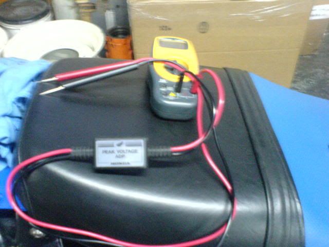 Here you can see the stator and pick up coil (top left, inside cover): 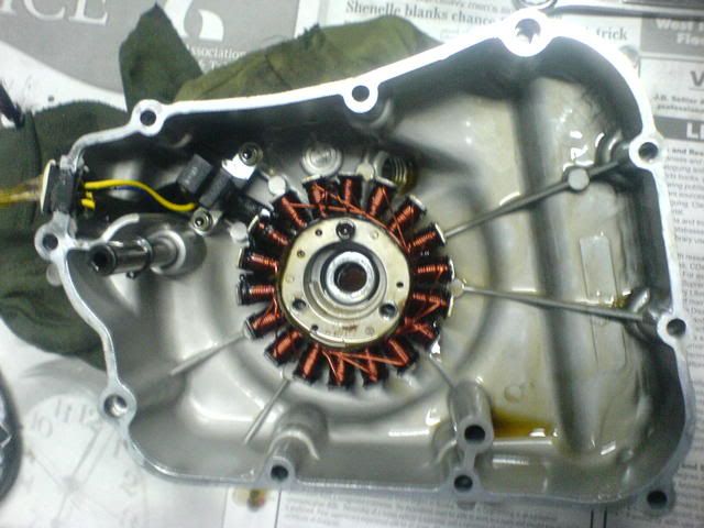 The Flywheel nut looks like it was installed with a pliers or pipe wrench: 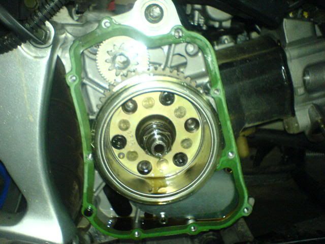 Another interesting find is, that the crankshaft seal in the side cover was damaged during factory installation. You can see the spring, which is normally around the sealing lip, across the opening. The sealing lip got damaged as well, could be because of the chamfer on the crankshaft, it has a couple of rough spots on it. This cannot happen during removal, only during installation, when lining up one has to lubricate the seal and be care full to center the shaft, before pushing it together: 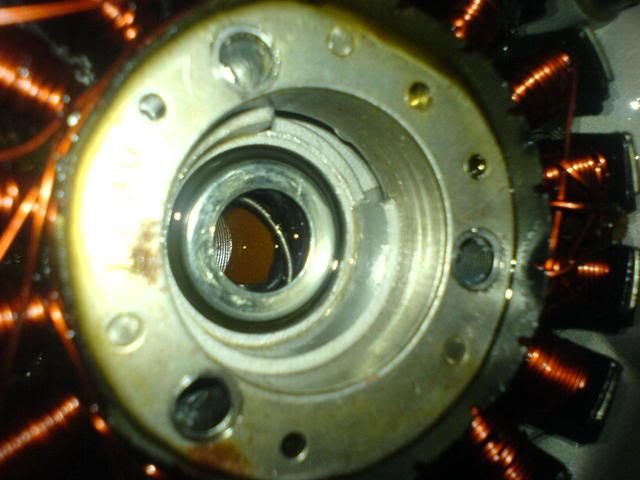 The moral of the story: "This is what can be expected with a Chinese bike and certainly can be expected from EVO Sales aka Rony and Moises, but you may not expect support from EVO Sales for Road Runner, they where done with me a good while back"Andi |
|
|
|
Post by scooterollie on May 30, 2008 20:34:42 GMT -5
Andi,
I sure hope you get your scoot back on line soon. Sorry to hear about the problem but sounds like you have the cause nailed. Interesting about the crappy assembly. I wonder where the Linhai design engines being used in the other make scoots actually come from?
|
|
|
|
Post by Andi on May 30, 2008 21:18:18 GMT -5
Andi, I sure hope you get your scoot back on line soon. Sorry to hear about the problem but sounds like you have the cause nailed. Interesting about the crappy assembly. I wonder where the Linhai design engines being used in the other make scoots actually come from? Good question, beats me. I think its a clone of a clone (of a clone?). Didn't even have an engine number on it just a sticker where the number is supposed to be. Hope I can get the parts. Andi |
|
|
|
Post by scooterollie on May 31, 2008 7:23:13 GMT -5
If you are referring to the engine family #, etc., look on the top edge of the CVT drive case - near where the left rear shock attaches. May be covered w/some dirt.
|
|